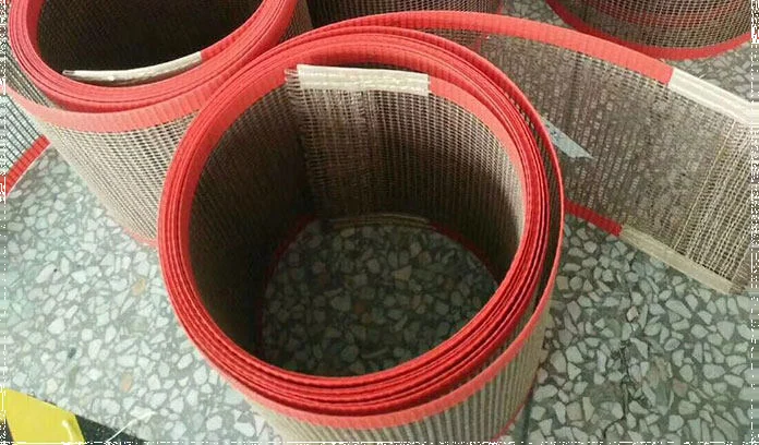
How do you choose a PTFE mesh conveyor belt?
Choose a PTFE mesh conveyor belt as a complete moving assembly. First establish how much support the product needs and whether air must pass through the belt. Then select the mesh construction, confirm the temperature rating of the finished assembly, and match the joint, reinforced edges and guides to the conveyor. Finish with a trial under the actual process load.
A description such as ‘4 × 4 mesh, black, heat resistant’ leaves open area, electrical properties, finished circumference and seam construction unresolved. These details can change performance even when two belts look similar.
Open mesh is useful in drying and curing when the process requires through-belt airflow. A closed surface is worth considering when small loose parts, surface marking or continuous support matter more. Taconic’s open-mesh overview describes this distinction between air-permeable mesh and continuous PTFE-coated belting.
This guide focuses on industrial dryer and curing conveyors. A roll of mesh or a cut panel is a material format; it becomes a conveyor belt only after its dimensions, end connection and machine interfaces are specified.
Start with the process, then define the construction
Begin with the product travelling through the machine. Record its smallest unsupported dimension, whether it softens when hot, and whether a mesh or seam imprint is acceptable. Include carriers, fixtures and trays in this assessment; the belt supports whatever actually contacts it.
Next record the process: hot air, infrared or another heat source; the measured belt exposure; belt speed; loading pattern; and the required exit condition. An open mesh can support air circulation, but it does not establish a drying rate on its own. The carried product, supporting bed and chamber airflow can limit the effective air path.
| Decision | Specify | Reason |
|---|---|---|
| Product support | Smallest product or carrier, hot-state shape and allowable marks | The load must remain supported across apertures and the joint |
| Mesh geometry | Clear aperture in both directions, open area and thickness | Aperture describes the gap; open area describes the proportion of exposed space |
| Material grade | Coating, reinforcement, operating conditions and electrical requirement | The coating name alone does not rate the complete belt |
| End connection | Joint style, pin, orientation and access for fitting | The joint changes local thickness, flexibility and airflow |
| Machine interface | Finished dimensions, rollers, bed, guides and take-up | A suitable mesh still needs a compatible conveyor |
Mesh opening and open area are different specifications
Mesh opening is the clear gap between neighbouring coated yarns. Open area is the percentage of projected mesh area occupied by those gaps. Neither is the number of openings per inch. Ask whether a supplier’s quoted mesh dimension means clear aperture or centre-to-centre pitch, and whether it is measured before or after coating.
For an ideal rectangular repeating cell, let ax and ay be the clear opening dimensions. Let wx and wy be the projected widths of the yarn bands that reduce those openings. The pitches are ax + wx and ay + wy.

With a 4 × 4 mm opening and 1 mm bands, the calculation gives 64%. The same opening with 2 mm bands gives about 44.4%. A mesh-opening label therefore cannot establish the open area by itself. Real yarn shape, coating build-up and weave distortion require measurement of the finished mesh.
Use open area together with support and airflow data
A larger clear opening may help air passage, but a small component can fall through it, a softened product can sag into it, and a carrier can cover most of it. Geometric open area is not an air-permeability test or a prediction of fan flow. Compare materials at stated airflow-test conditions where data are available, then validate the loaded conveyor.
Edge bands and a closed splice also occupy space. For planning, usable process width equals total finished width minus the two edge widths and any required side clearances. A hypothetical 1,000 mm belt with two 25 mm edges leaves 950 mm between the bands, before machine clearances. Check that the product path remains inside this usable zone.
Confirm the reinforcement, temperature rating and electrical properties
PTFE is the release coating. Glass fibre, aramid or a hybrid weave provides the load-bearing structure. Comparing only the coating overlooks the construction that experiences repeated bending and tension.
| Construction | Selection question | Evidence to request |
|---|---|---|
| PTFE-coated glass mesh | Does the grade suit the load, roller diameter and thermal exposure? | Finished thickness, directional strength data and recommended service conditions |
| PTFE-coated aramid or hybrid mesh | Does the construction address the required mechanical duty without compromising the thermal or moisture requirement? | Exact reinforcement, grade data and temperature limits for that construction |
| Specified antistatic mesh | What electrical behaviour is required by the process? | Resistance range, test method and conditions, plus compatibility with the machine’s grounding design |
Published ranges belong to particular grades. For example, Techbelt’s open-mesh data sheet lists an upper temperature of 260°C for the material it describes. Its mesh-grade tables show that other constructions have different limits. Neither establishes a rating for an unspecified WOLTOOL belt, its pin or its edge assembly.
State actual continuous exposure, short peaks, heating method and any steam, cleaning agent or chemical contact. Request confirmation for the complete belt, including the splice and guides. A chamber setpoint is not necessarily the hottest temperature reached by the moving belt.
Black colour alone does not establish antistatic performance. Taconic distinguishes black-pigmented belting from its antistatic grades. Specify the required electrical test rather than approving a sample by colour.
Likewise, a tensile result in N/50 mm is a test-strip result, not a permitted machine-tension setting. Confirm the test direction, method and conditions, then ask the belt supplier to approve the operating tension for the selected width, seam and temperature.
Choose the joint for airflow, fitting access and surface contact
A seam crosses the product path on every revolution. It can introduce a height change, a less open strip or different bending behaviour. Consider both whether the belt can be fitted through the conveyor and what the product experiences when the joint passes underneath.
| Joint family | Useful feature | Check before approval |
|---|---|---|
| Bullnose or fabric-loop joint with a pin | Open connection that can be closed on the machine | Loop attachment, pin retention, finished profile and smallest roller compatibility |
| Metal spiral, clipper or alligator connection | Mechanical connection with accessible disassembly | Metal contact, clearance, pin security and possible product marking |
| Non-metallic spiral or lacing | A route when exposed metal is undesirable | Exact lacing and pin materials, thermal limits and bending clearance |
| Bonded overlap | Continuous joined strip | Local loss of open area, added thickness and fitting access |
Techbelt’s connection guide describes these joint families and notes that bonding an overlap in open mesh blocks the apertures in the joined zone. Availability and performance depend on the belt construction.
A removable pin connection and an endless bonded belt require different installation access. Obtain a cross-section or sample of the proposed seam. Ask for assembled thickness, approved bend direction, minimum roller diameter and a retention detail for the pin. Check the joint square to the belt edges: a skewed seam introduces a geometric error that stronger edge bands do not remove.
Separate edge reinforcement from the tracking system
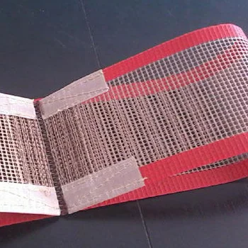
Edge reinforcement protects and supports the belt edge; a tracking device interfaces with the conveyor to control its position. They often work together, but specifying one does not specify the other.
Film bands, coated-fabric bands and sewn-and-sealed fabric edges are documented fabrication options in Taconic’s belting overview. Guides may use cords, snaps or other hardware. Review each option against the actual conveyor; these examples are not a statement that every format is available for every mesh grade.
- Edge width and thickness: define how much process width the bands occupy and their clearance over rollers and the bed.
- Band attachment: confirm the bonding or stitching construction and how it withstands the specified heat and repeated bending.
- Guide location: show the conveying side and pulley side, guide profile, offset from the edge, and mating groove.
- Hardware interfaces: if the machine uses studs or eyelets, provide diameter, pitch, position and photographs. Do not substitute a different pattern without checking the equipment.
During replacement, copy the interface details from an approved drawing or an undamaged reference area. A torn edge can reveal the failure mode, but it is a poor dimensional reference for a new guide. Reinforcement should not be used to make a belt rub continuously against a machine frame.
Define finished dimensions, roller clearance and take-up
Specify finished belt width and finished closed circumference, with units and the measurement condition. The cutting length before joining is not necessarily the closed circumference. Identify the reference temperature, whether the sample is relaxed or measured under an agreed load, and how the joint is assembled during measurement.
Record the smallest roller that the belt or joint bends around, including return rollers. Also record any reverse bend. Do not infer the required diameter from mesh thickness alone: the seam, edge bands and guide profile may set a different limit. Obtain approval for the full assembly.
Check the conveyor, not only the worn belt
Use the original machine specification where available, then check the installed layout and take-up position. A belt measured after wear, stretching or edge damage may reproduce the previous problem. Record the available adjustment range and whether a replacement can be installed without exhausting that range.
For a simple two-roller layout with equal effective roller diameter D and centre distance C, the ideal path estimate is L ≈ 2C + πD. With C = 1,500 mm and D = 100 mm, that is approximately 3,314 mm. This is only a geometry example: extra rollers, belt thickness, splice construction and take-up change the manufacturing requirement. Use an approved drawing or agreed measurement for the order.
Allow for the support bed
Check roller alignment, bed support and clearances in the hot operating condition as well as cold. Thermal movement can change support and clearance. Product loading concentrated in the centre can also behave differently from an evenly distributed load. Give the supplier a layout drawing rather than assuming any belt of the right width will run on it.
Use failure patterns to investigate tracking and wear
Replacing a damaged belt with a heavier construction may leave the original machine problem unresolved. The following patterns are diagnostic leads to investigate with the machine and belt suppliers.
| Observed pattern | Checks to prioritise |
|---|---|
| Damage mainly along one edge | Side contact, roller alignment and guide position |
| Tracking changes when heated or loaded | Hot-state frame geometry, bed support and loading distribution |
| Wear concentrated at each seam passage | Seam profile, roller clearance and product contact |
| Broken yarns or a growing tear | Snags, local rubbing, bending damage and tension history |
| Periodic mark on the product | Whether the repeat distance matches belt circumference and seam passage |
Techbelt’s conveyor recommendations emphasise aligned rollers, adequate support and no more tension than needed to drive the belt. Treat these as selection principles; adjustment values and tracking procedures must come from the machine and belt suppliers. A generic rubber-belt tension rule is not a specification for coated glass mesh.
Inspect and service according to the machine’s isolation, cooling and access procedures. Record photographs, temperature, loading and the location of damage before deciding whether to change the belt construction.
Approve the mesh, then validate a finished trial belt
A flat swatch helps compare aperture, surface and product support. It cannot validate the seam, tracking system or performance after repeated bending. Use a finished trial belt when those interfaces are critical.
- Receiving checks: verify grade identity, finished width and circumference, aperture units, seam assembly, edge width, guides and visible damage against the agreed drawing.
- Mechanical trial: have qualified personnel check clearance and tracking using the machine’s prescribed procedure, then assess representative loading.
- Process trial: record measured belt exposure, speed, loading, exit condition, marking and release. Include the area crossing the seam.
- Repeatability: retain the approved sample or construction record and agree which dimensions, properties and process outcomes will be checked on repeat orders.
Example: separate dwell time from drying performance. A 3 m heated path at a belt speed of 1.5 m/min gives a nominal transit time of 2 minutes. The calculation is heated path length ÷ speed; it does not establish product temperature or sufficient curing.
When comparing two meshes, first hold the process settings and loading comparable, then measure the resulting exit condition. If higher throughput is the goal, agree the acceptance condition before testing a speed increase. These are planning examples, not measured production results.
A useful trial record identifies the candidate grade, joint and edge construction alongside the operating conditions. Report what was observed rather than attributing every improvement to a larger aperture.
What to include in a PTFE mesh conveyor belt RFQ
Send a marked drawing, photographs and the following information. An incomplete value can be marked for confirmation; it should not be guessed from an image or a shorthand stock description.
- Machine make/model, layout, process and reason for replacement
- Finished width and closed circumference, units, tolerance and measurement condition
- Clear mesh opening in both directions, open-area requirement or reference grade, and finished thickness
- Smallest product or carrier, loading pattern, belt speed and acceptable surface marks
- Continuous belt exposure, short peaks, heating method and any steam or chemical/cleaning contact
- Smallest roller diameter, reverse bends, support bed, take-up position and available adjustment
- Joint type, assembled profile, pin material/retention and fitting access
- Edge material, width, attachment and guide/hardware dimensions with positions
- Electrical or other application-specific requirements with test method and required documentation
- Trial quantity, production quantity, required delivery date, packing and acceptance criteria
Review the matching WOLTOOL product formats
For a finished replacement belt, start with PTFE open-mesh dryer conveyor belts. For mesh rolls or cut panels, review PTFE-coated fiberglass mesh. If the process needs a continuous release surface, compare PTFE-coated fiberglass fabric; fabric supplied by the roll is not automatically a finished belt.
The current dryer-belt listing includes a 1 m width entry and opening labels such as 0.5 × 1, 1 × 1, 2 × 2.5, 4 × 4 and 10 × 10. Some source labels omit units or complete belt dimensions. Confirm whether they describe clear openings in millimetres, the full grade and the finished assembly before ordering. These entries do not establish an open-area percentage, a tension limit or a complete temperature rating.
Send the machine details and belt specification for review. Joint options, supply format, sample availability, MOQ and lead time are confirmed for the selected construction.
FAQ
Does a 4 × 4 mm mesh opening mean 64% open area?
No. Open area also depends on projected yarn width and the finished weave. In an ideal square example, a 4 mm opening with a 1 mm yarn band gives 64%; with a 2 mm band it gives about 44.4%. Ask for the finished-mesh aperture and measured open area.
Which joint is best for a PTFE open-mesh dryer belt?
There is no universal best joint. Open loop or spiral connections are candidates when through-belt airflow and on-machine fitting matter. A bonded overlap creates a less open strip. Confirm the proposed joint against roller diameter, temperature, product contact and maintenance access.
Can every PTFE mesh conveyor belt operate at 260°C?
No. Some published glass-based grades list 260°C, but the ordered assembly needs its own confirmation. Reinforcement, seam, pin, edge construction and actual exposure may set different limits. The chamber setpoint alone does not rate the belt.
Is every black PTFE mesh belt antistatic?
No. Pigmented black and antistatic constructions are different specifications. Request the resistance range, test method and conditions for the exact grade, and verify compatibility with the machine’s electrical design.
Will reinforced edges stop a conveyor belt from tracking off?
Reinforced edges protect the belt boundary and support attachments. They do not correct every alignment, tension, support or loading problem. Match any guide to the conveyor and investigate why the belt is moving sideways.
Is a PTFE mesh roll the same as a finished conveyor belt?
No. Roll stock or a cut panel supplies the mesh material. A conveyor belt also needs confirmed finished dimensions, an end connection and compatible edges or guides. State which supply format you need in the RFQ.
Can a used belt be the only reference for a replacement?
Use an approved drawing or machine specification when possible. A worn belt can be stretched, distorted or missing part of its guide. Record its measurement condition, the conveyor’s take-up position and the full joint and edge details before approving replacement dimensions.
Technical references
Manufacturer publications support the general selection principles discussed above. Their grades, test values and approvals apply to their own products; confirm the specification of the belt being ordered.
- Taconic — Open Mesh BeltingOpen-mesh construction, reinforcement families and airflow applications.
- Techbelt — PTFE Open Mesh Belts Data SheetPublished material information for the supplier’s specified open-mesh belt.
- Techbelt — PTFE Coated Mesh FabricGrade-specific construction and service-temperature comparisons.
- Techbelt — PTFE Conveyor Belt Connection TypesLoop, spiral, mechanical and bonded connection designs.
- Taconic — Conveyor BeltingEdge reinforcement and guiding-device fabrication options.
- Techbelt — Conveyor Recommendations for PTFE BeltsGeneral principles for rollers, support, tension and tracking.
- Taconic — Tac-Black BeltingDistinction between pigmented black and antistatic belting.